- Home
- Assembly AND PARTS LIST
- PROJECTS
- BUY
- EMF, MONOSTABLE, COUNTER
- PIC BASIC EXAMPLE PROGRAM
- LOGIC GATE EXPERIMENT
- LDR AND VCO VIDEO
- LAB VIDEOS
- MORE
- ARDUINO
- CONNECTION TO WS2811 LEDS
- 24 BIT SHIFT REG CODE
- 24 BIT SHIFT REG CODE (2)
- USING SHIFT REGISTERS
- DRIVING A STEPPER MOTOR
- CASCADED DOT MATRIX DISP
- LED LABS SILK SCREEN
- SOME EXPLAINED SCHEMATICS
- LOGIC TRUTH TABLES
- LEDLABS VIDEO
- LED LAB & GOLDEN SPIRAL
- SIGNAL DEGRADATION
- TRANSISTOR OUTPUT TEST
- LOGIC GATES
- CHOOSING POTENTIOMETERS
- LOTTERY GENERATOR IDEA
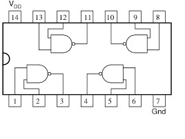
NAND FUNCTION
Logic gates such as the quad 2 input nand, (4011) has four separate nand gates in one package, the truth tables for some of these devices are listed opposite A 4011 can be placed in the ZIF (zero insertion force) socket, and pin 14 wired to +5v, and pin 7 wired to 0v. pins 1 and 2 are inputs and pin 3 is the output of this gate (one of the four). If the 2 x button command pulled down switches are used on Ledlabs and a wire connected from their outputs to the inputs 1 and 2 of the nand gate, (this represents the inputs) and pin 3 connected to the monostable input, (this represents the output of the nand gate)
If a wire was taken from the latch out of this monostable to the clock in of the decade counter, it would show the conditions of the nand gate's output using switches as inputs. As it stands, wired as described both inputs are low 00, then pressing one of the switches 01,(logic 1 on one switch and logic 0 on the other) then 10,(the other combination) nothing happens, when 11 (both switches pressed logic 1 for both) it triggers the output of the gate to a logic 0 which the monostable requires to activate it, (as it is active low), this means the output is logic 0 only when the two inputs are logic 1. (if a wire were taken also from the output to an led, (1 of the 8) this would be lit until both switches are pressed also showing the gates output function and can be connected while the other modules are.). This can be seen by looking at the truth table for the nand gate. Other logic gates and types can be tested by these sorts of methods by way of triggering modules on led labs.