- Home
- Assembly AND PARTS LIST
- PROJECTS
- BUY
- EMF, MONOSTABLE, COUNTER
- PIC BASIC EXAMPLE PROGRAM
- LOGIC GATE EXPERIMENT
- LDR AND VCO VIDEO
- LAB VIDEOS
- MORE
- ARDUINO
- CONNECTION TO WS2811 LEDS
- 24 BIT SHIFT REG CODE
- 24 BIT SHIFT REG CODE (2)
- USING SHIFT REGISTERS
- DRIVING A STEPPER MOTOR
- CASCADED DOT MATRIX DISP
- LED LABS SILK SCREEN
- SOME EXPLAINED SCHEMATICS
- LOGIC TRUTH TABLES
- LEDLABS VIDEO
- LED LAB & GOLDEN SPIRAL
- SIGNAL DEGRADATION
- TRANSISTOR OUTPUT TEST
- LOGIC GATES
- CHOOSING POTENTIOMETERS
- LOTTERY GENERATOR IDEA
LOGIC GATES
Logic gates are fundamental in computers and micros, in the digital world of computers which uses two conditions 0’s and 1’s, high or low or boolean expressions like true or false, logic gates allow millions of conditions/second to cascade through complex systems. Analogue has an infinite range of values whereas digital has only two. Some of the technology types used are CMOS (complementary metal oxide semiconductor) and TTL (transistor transistor logic). each having different qualities.
CMOS has a wider fan out of gates, can work on various voltage supplies and uses less power, so it is suitable for battery operation, however it is slower than TTL.
TTL is very fast can only work on 5v and uses more power than CMOS. In old CMOS calculators there was a noticeable pause in getting the answer from a calculation due to the propagation time delay, mainly due to cascading through the large fan out of gates and other factors.TTL was much faster and appeared instant but not that suited to battery operation. In the early days CMOS liked LCD displays running on batteries and TTL favoured led displays running on desktop calculators plugged in.
TTL use BJT bipolar junction transistors, and CMOS uses FET field effect transistors., BJT’S requires more current than FET’S. These two types can be interfaced together using pull-up resistors.
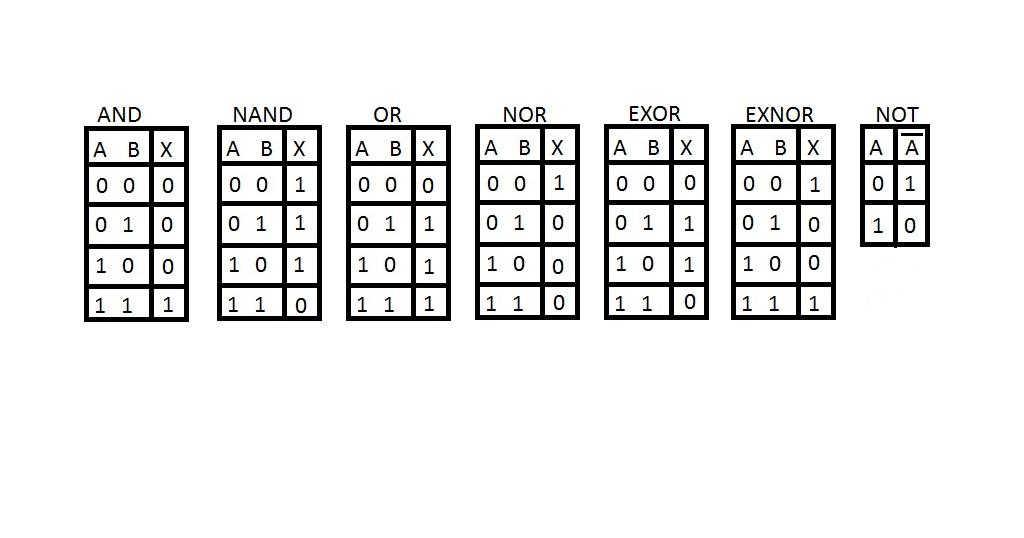
Below are some logic gates and there truth tables: All unused gate inputs should be tied to a level 5v or 0v, to stop the logic levels from floating, which can give spurious results, outputs should not be directly grounded or damage would occur.